| | Unidentified part |  |
|
|
| Author | Message |
|---|
Rod Clay
Technician


Join date : 2018-08-01
 |  Subject: Re: Unidentified part Subject: Re: Unidentified part  January 11th 2020, 6:51 pm January 11th 2020, 6:51 pm | |
| Well, yes the shortwave bands are still open to and assigned to short wave broadcasting stations and amateur radio operators. I am talking about the range from 1.8 MHz to 30 MHz except that there aren't as many broadcasting stations on as there used to be. The old AM Broadcast band has been extended to 1710 kHz so some new stations can be found in the upper part of that band. A lot of the old shortwave stations have quit broadcasting altogether or moved to the internet for their services. Some frequencies have been reassigned. There are a few new amateur radio bands and some of the remaining broadcasting services can be found in parts of the older amateur bands such as on 75 Meters and 40 Meters at different times of the day depending on where you live. We consider these to be unwanted broadcasts or QRM in "our" bands. However, there must still be some listeners out there for them that may need to hear those broadcasts. Regarding the "bandspreaded" shortwave bands some of these old radios featured: These made tuning in a station a lot easier back when the bands were so crowded. You may not find many stations in them now. They have moved to other frequencies or just quit broadcasting altogether. Hope this helps.
73, Roderick WB6FBF
P.S. There are various broadcasting stations out there (at various times of day) that you could use to to help align your radios. You can get some signals from the Local Oscillator in an ordinary (modern) AM radio in the range from about 975 kHz to 2165 kHz. Then there will be harmonics of those frequencies that you could make use of too. Sorry. I can't think of any stations that are currently broadcasting on 455 kHz that might help you with an IF alignment. If you are into building you could put together a simple oscillator for 455 kHz with a small ceramic filter unit - that is if you can't get a real 455 kHz quartz crystal. There is also a lot of test equipment out there that needs a home and is relatively inexpensive to buy even by today's standards. |
|
 | |
Glayone06
Beginning Member
Join date : 2020-01-08
| | Subject: Re: Unidentified part January 11th 2020, 5:48 pm | |
| - Rod Clay wrote:
- That is all very interesting. I was thinking that if it was a small value capacitor of some kind it probably could be disconnected and not cause any major problems on that particular band (shortwave). However, now I realize these sets do have one or two bandspreaded shortwave bands on them so it might have some effect there on the calibration. Regarding C16: I was looking at the wrong schematic diagram! The info I sent before was for chassis 101.614 not 101.613! Sorry about that. Now that I think about it, I am sure that I had one of these radios back in Lynchburg Virginia. It was a floor model console and a good performer. It had (2) bandspreaded short wave bands on it so I guess it used the 101.614 chassis. Good luck with yours.
Rod WB6FBF
P.S. I only had trouble with the audio output transformer in it. The primary winding was open when I got it. After replacement and the usual recapping the set worked well but eventually the output transformer opened up again. I must have missed something there.
Rod Thanx, rod. I haven't really determined if the bands are all working yet. I did hear WWV on one band so I know that one is working. I'll have to figure out which band the cap has an effect on & take it from there. I'll probably just start haning some different silver mica caps in there & see what happens. Thanx again for all your help. BTW, are the std SW bands on these old radios still assigned to broadcast stations that they were back in the day? I re-capped another 1940's radio & could not receive any intelligible audio anywhere on the dial. I am not really intending to continue repairing the old radios so I am not intending to procure any signal generators, so I'm really at a disadantage not being able to generate a station to determine if it's functioning other than trying to tune an on-air broadcast. I just thought perhaps as many old bands were re-allocated to frequencies like the police & such on digital communications if that might have happened to some of the old std SW bands... |
|
| | |
Rod Clay
Technician
Join date : 2018-08-01
| | Subject: Re: Unidentified part January 10th 2020, 4:49 pm | |
| Yes. I didn't spend enough time on that radio but then I still had some things to learn about the circuitry and why various parts were included in the chassis. The cabinet was in bad shape so that didn't help but I did enjoy operating it while it was working. Some of my later work with radio transmitters helped out with figuring which parts to keep and what to replace.
Back then I was mostly concerned with trying to prevent B+ to ground shorts and getting any leaky coupling capacitors out of the circuit. In the audio stages I used to routinely cut out any tone capacitors and the various configurations of output plate to ground, and plate to cathode "bypass" capacitors. I also would cut out any plate to plate caps used in push-pull stages and plate to B+ capacitors because I figured they would still be leaky and somehow cause problems. Back in those days I didn't replace those caps. Not replacing those caps in the output stage is a bad practice as I have found out the hard way. They have several functions in those circuits. I think it likely that the radio I had back then used the Silvertone 101.614 chassis so please refer to that diagram.
As I said before, after I got the set I found out that the push-pull output transformer primary was open on one side. Far as I can recall, I didn't look into why this might have happened just that I replaced the transformer with another from the junk box and replaced the coupling caps and most likely just cut out the others. The chassis uses (2) "tone" control caps in the circuit connected from plate to plate and switched in for High, Medium and Low response. If I had left these in they might have helped assuming one or both were switched in most of the time that I had the radio on. There is also a 56 Ohm resistor in the plate lead of each 6F6 tube (R27 and R28) which was probably put there to suppress parasitic oscillations of some kind. The oscillations could be supersonic or even higher. I doubt if I looked at those resistors. Then there are the (2) .001uF caps connected from the junction of the 56 Ohm plate resistors and the tone caps to their respective 6F6 cathodes.
I can only think looking back that without at least those .001uF caps in place that either one of two things were going to happen (again). That one of the 6F6 tubes would open up (from surges or parasitic oscillations) or that one side of the output transformer would open up again. Well, the transformer did open up again. I think I did confirm that one side of it opened up but beyond that I did no more work on it.
73, Roderick WB6FBF |
|
| | |
Cliff Jones
Site Administrator


Join date : 2010-11-22
| | Subject: Re: Unidentified part January 10th 2020, 9:52 am | |
| If the transformer opened, then the first thing would be suspect is a shorted Capacitor, Then a (opened?)resistor. if it were open then the voltage may exceed the transformer voltage rating. Also a shorted tube. note: I have removed previous posted  duplicate pictures. 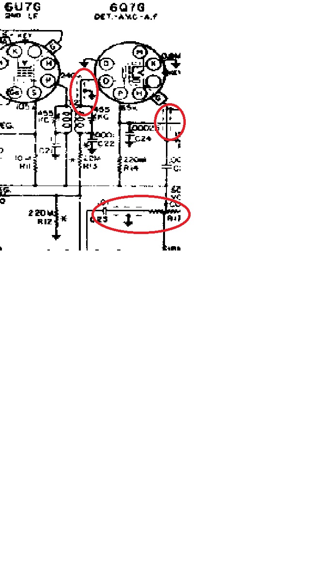 look at if transformer T2 up to tube # 6Q7G connector . also the volume control to c13? to switch on the bottom.
_________________
I'm a Science Thinker, Radio Tinkerer, and all around good guy. Just ask Me!
|
|
| | |
Rod Clay
Technician
Join date : 2018-08-01
| | Subject: Re: Unidentified part January 10th 2020, 4:10 am | |
| That is all very interesting. I was thinking that if it was a small value capacitor of some kind it probably could be disconnected and not cause any major problems on that particular band (shortwave). However, now I realize these sets do have one or two bandspreaded shortwave bands on them so it might have some effect there on the calibration. Regarding C16: I was looking at the wrong schematic diagram! The info I sent before was for chassis 101.614 not 101.613! Sorry about that. Now that I think about it, I am sure that I had one of these radios back in Lynchburg Virginia. It was a floor model console and a good performer. It had (2) bandspreaded short wave bands on it so I guess it used the 101.614 chassis. Good luck with yours.
Rod WB6FBF
P.S. I only had trouble with the audio output transformer in it. The primary winding was open when I got it. After replacement and the usual recapping the set worked well but eventually the output transformer opened up again. I must have missed something there.
Rod |
|
| | |
Glayone06
Beginning Member
Join date : 2020-01-08
| | Subject: Re: Unidentified part January 9th 2020, 9:05 pm | |
| BTW, have you-all visited Mr. Carlson's Lab site on YouTube? Very interesting dude. Super knowledgeable. Even as long as I've been in the repair field, I'm still learning things from this very informed, intelligent, rather 'normal' cat. g |
|
| | |
Glayone06
Beginning Member
Join date : 2020-01-08
| | Subject: Re: Unidentified part January 9th 2020, 9:03 pm | |
|  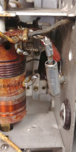 Thanx for all the replies! From the 101.613 Schemo from Riders (vol12 pg4 of the Sears section), it appears this is C16. It is designated by a capacitor symbol with an arrow on one of the plates of the capacitor. No value listed. I've never seen that designation...I'll try to look it up. Antique radio repair was not my forte' tho I messed with a bunch of them when I was a kid not having a clue about anything. I suppose it could be some kind of temp compensating cap as Rod Clay indicated. It is merely what appears to be a copper wire of about 10 or 12ga stuck inside an aluminum can with no insulator and as I mentioned a spring in the bottom of the can that the wire perches on. The 'wire' in crimped to a connector giving the impression that it is not copper at all and not solder-able. I'll attach a pic of it pulled apart. There is nothing to keep the inside electrode from shorting to the can. I suppose whatever insulator they may have had has long since disintegrated. I guess I could try to position it so it's not shorting & then silicone glue the end like that. I imagine the end with the spring on it would be insulated from the can or perhaps the end of the wire is isolated from the wire. I'll have to do some more investigation there. A thought I had was perhaps as the temp rises the spring expands and changes the capacitance by pushing the wire further out of the can?! Crazy idea but maybe not so much for 1940. Rod, Not sure which schemo you're looking at but in the one that I have that seems to follow the actual radio shows C16 going to ground from on of the oscillator coils, so I'm thinking you may be looking at another version or something. Here's the link to the Volume with the schematic I'm viewing:Vol 12 pg 4 Sears Thanx all for your help. At this point after replacing all the wax caps & electrolytic s, I get SW WWV but only whistling on the other bands...got some work ahead & alignment, too. Glen Whatley - Mars Amp Repair... BTW, you could never charge commensurate to the amount of time it takes to replace all those caps, especially the ones that are buried below the oscillator coils, etc. It's just a labor of insanity! DANG! Went & uploaded 4 of the images. Gotta figure out what I'm doing wrong.... |
|
| | |
Rod Clay
Technician
Join date : 2018-08-01
| | Subject: Re: Unidentified part January 9th 2020, 2:37 pm | |
| Cliff,
OK. Thanks. I did find it at Nostalgia Air after all. It is a 1940 model set.
Glen, C16 appears to be labeled as 50 pF (.00005 uF) on the schematic I looked at. It is somewhat hard to read and make out as usual in Rider's. C16 is the oscillator grid coupling capacitor for the 6K8G converter stage. The part you asked about does not appear to be that one. Pictures can be deceiving (I know that from eBay) and without the set in front of me it is hard to say what it is but that side connection on it does appear to be grounded to the chassis (that red mica cap looks to be soldered to it above there). The only fixed capacitor not labeled in the oscillator section is C20 and it does go to the bandswitch as well as to L3. The part you asked about may be that one.
Cliff, I looked and looked and couldn't find a C25. C3 in the antenna lead is the only .01uF cap I can see that goes to either the bandswitch or coil assemblies. |
|
| | |
Cliff Jones
Site Administrator
Join date : 2010-11-22
| | Subject: Re: Unidentified part January 9th 2020, 1:25 pm | |
| C25? .01 uuf it looks like a feed-thru capacitor
and on the schematic it has dashed lines top and bottom.indicating a feed-thru
Rod its located in Riders book 12, Silvertone pages number 6.
The Model number is R81
_________________
I'm a Science Thinker, Radio Tinkerer, and all around good guy. Just ask Me!
|
|
| | |
Rod Clay
Technician
Join date : 2018-08-01
| | Subject: Re: Unidentified part January 9th 2020, 1:14 pm | |
| Well, since it is attached to the bandswitch it is part of the RF section of the radio. That is a clue. Before I saw it, I thought it might be a button cell bias battery holder but it can't be that.
It may be a low value capacitor (a few pF) possibly a temperature compensating type if that is the oscillator coil next to it. I have seen a few examples of early temperature compensation attempts in late 1930s multi-band receivers. The Hammarlund HQ-120 receiver comes to mind. This was before ceramic compensating types became commercially available.
When it is not switched into the circuit can you get any kind of a reading on it? I only ask because you said there was something that looked like a spring in there at the bottom of it. If it is not causing any problems on that particular band when it is switched in then I would suggest leaving it alone. If it is only switched in on the highest frequency band then it is more likely to be a temperature compensating cap.
73, Roderick WB6FBF
P.S. I took a look for the schematic of your radio at Nostalgia Air but it wasn't listed there. Then I looked at the free 120,000 schematic page of nuco.com (they sell loose gem stones too?) you mentioned but couldn't figure out how to find it or even do a search for it. I guess I am not good at finding things hi, hi.
Rod |
|
| | |
Glayone06
Beginning Member
Join date : 2020-01-08
| | Subject: Re: Unidentified part January 8th 2020, 9:29 pm | |
| Trying to add the schemo....For some reason it won't allow me to attach this PDF. Sorry...glen |
|
| | |
Glayone06
Beginning Member
Join date : 2020-01-08
| | Subject: Unidentified part January 8th 2020, 9:26 pm | |
|   Hello. My name is Glen and I'm new to the forum but by no means new to old electronics. I am in the process of recapping this old Silvertone console chassis #R41 101.613. There is one component that is in the attached pix. To the best I can determine, it is labelled as C16 in the schematic but that doesn't jive with how it is actually connected in the radio. If it is C16, the schematic has no value for it. There is no parts list only what is labelled on the schematic. It is bascially what looks like a piece of copper wire that has a crimp connection on one end and then just is stuck in a hollow metalic cylinder. It also appears that there is a spring in the base of the can that the wire sits in...there are no markings on the can. How you see it in the pic is how I found it. Any ideas? I'll try to attach the schemo, too. I found it no nucow.com. A wonderful site with nearly all the old radio schematics for free.01.08.2020. Well, I'm just figuring out how to attach pix & have too many of the chassis & cannot figure out how to remove them. As a result I can't attach the schematic. I'll try responding to my own post and add the schemo there...thanx, Glen Whatley - Mars Amp Repair Nampa, ID. |
|
| | |
Sponsored content
| | Subject: Re: Unidentified part | |
| |
|
| | |
| | Unidentified part | |
|


